With the help of façades and pathways, their change in appearance is illustrated by different types of illumination.
Scenario 1
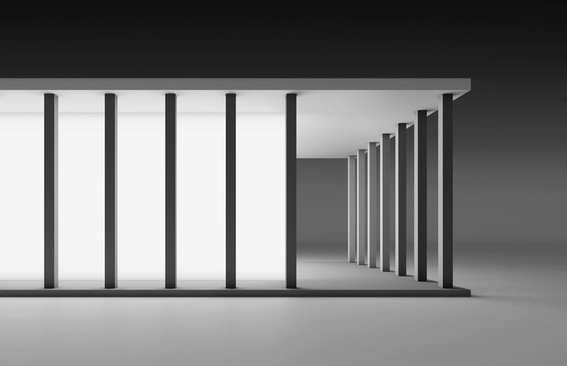
The most obvious form of lighting for a structure with a glass façade is that of the illumination of the interior. In the example, the illuminated cube is surrounded by pillars, which create a striking architectural image as black lines.
Scenario 2
In the following examples, the cube has a façade which is not illuminated.
The structure is framed by light from the ground. The building is illuminated uniformly from the ground to the roof. Since the pillars are positioned in front of the building, they cast shadows under the ceiling, and this could be regarded as too restless.
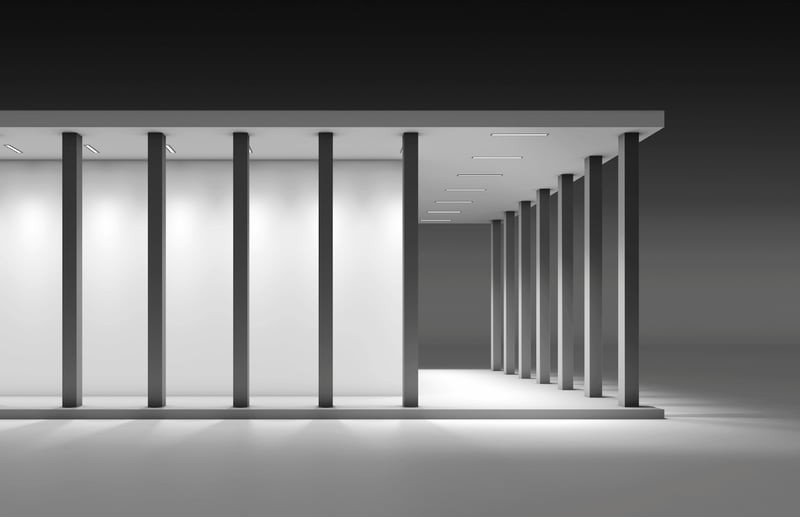
Scenario 3
Scenario 3 shows light being emitted from under the roof, directed straight at the floor of the arcades. The floor area is uniformly illuminated. From a distance, this light appears more restrained.
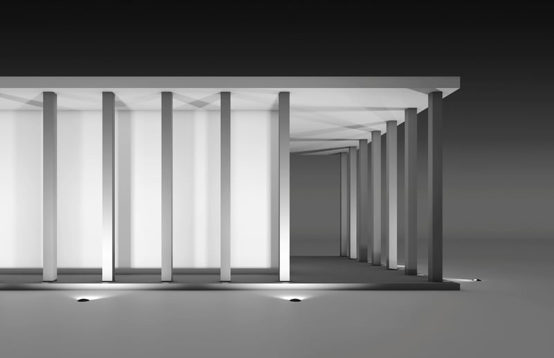
Scenario 4
Scenario 4
feels more spectacular. The light is emitted from the ground to the ceiling by long slim recessed floodlights. These are installed in the ground directly at the base of the pillars, and at the same time also illuminate the inward-facing sides. From a certain distance, the ceiling of the building appears detached from the glass cube.
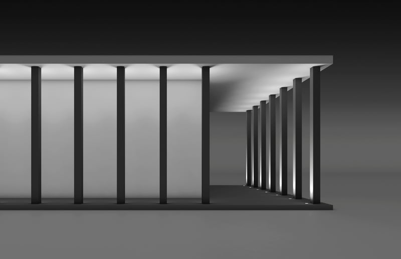
Scenario 5
The position of the luminaires has now been reversed. The light from the recessed floodlights installed outside in front of the pillars plays around the pillars and partially illuminates the ceiling. This type of illumination is very suitable for focusing on exciting architecture.
Scenario 6
If the public is an additional factor, it is possible to emphasise the ground surfaces with light within the arcades in addition to the illumination from scenario 5. This is done with recessed ceiling luminaires. In this way, functionality is combined with the exciting illumination of buildings.
Comparison of the visual effect of different heights of bollards with flat beam light distribution.
For pathways, the minimum degree of illuminance required is 0.6 -1 lx. This dictates the luminaire spacing. The basis is the light at the darkest place between the luminaires. In this way, low mounting heights lead to smaller distances between luminaires and thus to a larger number of luminaires. Higher mounting heights have the opposite effect.
Scenario 1
The large bollard has a mounting height of 1 m. The pathway is uniformly illuminated. The luminaire spacing is 9-10 m.
Scenario 2
Medium-sized bollard with a mounting height of 50 cm: the light is somewhat more accentuated. Here, the luminaire spacing is 5 m.
Scenario 3
Small bollard with a low mounting height (20 cm). On account of this low mounting height, bright areas are created in the direct vicinity of the luminaire. The light is accentuated. Recommended luminaire spacing of 2.5 m.
The light effect from a bird’s eye view
From above, the light distribution of the three bollards shown can easily be compared. The light distribution curve shown illustrates the degree of illuminance of 0.5 lx on the ground surface. This value is important for determining the maximum luminaire spacing. A slight overlapping of these light distribution curves is recommended, since the light in the overlapping area is added together and results in 1 lx, the minimum illuminance value required on cycle paths and footpaths.
On public paths, uniform illumination is important on account of safety-relevant aspects. The architectural environment in the public area is generously dimensioned. Here, higher bollards have a harmonious effect.
Smaller bollards are more common in private environments.
Scene 1 · Mounting height 1 m · Luminaire spacing 9 m
Scene 2 · Mounting height 0.5 m · Luminaire spacing 5 m
Scene 3 · Mounting height 0.2 m · Luminaire spacing 2.5 m